Visible Light Microscopy
Updated 3 September 2025

Contents
Use the browser "back control" to return here.
- Introduction
- Leitz Dialux Polarizing Microscope
- Microscopes For Beginners, Basic Microscopes, More Advanced Microscopes, Old Microscopes, Slide Preparation and Lighting, Useful References
- Eyepieces and Objectives, Suggested Additional Objectives
- Lighting, USB light Sources
- Choosing a Microscope Camera, Microscope Resolution, Camera Resolution, Field Curvature and Resolution, Resolution and LCD screens, Resolution and Publishing, Cameras and Trinocular Adaptors
- Four Omax Microscope Cameras
- Omax 1.3 MP Microscope Camera
- Omax 3.2 MP Microscope Camera
- Polarized Light Microscopy
- Polarized Light, Compensating Plates and Imaging, Sensitive Tint Imaging Improvements, Sensitive Tint the Low Cost Way
- Circular Polarizers, 3d Glasses as Circular Polarizers, Samples in Circular Polarized Light, Circular Polarizers on my Leitz Dialux Polarizing Microscope
- Dark-Field, Rheinberg and Circular-Oblique Illumination, Dark-Field Stops, Dark-Field Setup, Dark-Field Condenser, Rheinberg illumination, Circular-Oblique Illumination, Diatom Preparation, Berek Condenser
- Stereo Microscopes, My Stereo Microscopes, Stereo Microscope Photography
- Digitech 5 MP USB Microscope, USB Microscope Upgrade, ImageJ and Scale-Bars
- Pentax Macro Camera, Lenses
- Canon Macro Cameras, Macro Adaptors
- Publications
Introduction
This page is about my microscopes and how I use them. At this stage I own no modern microscopes but I do have some good examples of older ones.
I have upgraded all my microscopes with LED illumination systems, each running off a USB power source. Like in photography, good lighting is far more important than what camera or microscope is used.
These notes and links are for my use and also to help others. My limited experience with many areas of microscopy means there is a bias towards microscopes, techniques, lighting and image capture with a few of my samples as examples. I can't afford new research-grade equipment, so I try to achieve similar performance from selected low-priced or recycled alternatives. I have had a hard time with some topics, especially compensators for polarizing microscopes. I think I have now got it almost correct after quite a few revisions.
I operated and maintained a JEOL 733 Electron Microprobe for 12 years and I used several Polarizing Microscopes during and before that time. Prior to that I had a varied scientific career. I revise these notes as I progress and to correct mistakes. The photos shown here are scaled for the internet so some detail is lost.
On the right I have included a range of useful links, plus some images which can be enlarged by clicking on them.

Leitz Dialux Polarizing Microscope
My Leitz Dialux polarizing microscope is in good condition, with a performance matching that of a modern research microscope. It is a research grade microscope with 5 objectives on a rotating turret. It has a trinocular head which allows a camera to be fitted. There is a rotating stage supplemented with a precision x-y adjustable slide holder.
Two condensers are available with full adjustments. Correct condenser adjustment delivers excellent viewing results with this microscope. The adjustments, which are described in many textbooks, confine the light to nearly fill the lens apertures without touching, and reflecting off, any adjacent surfaces. This gives the best resolution and good contrast.
I used 12.5x Leitz Periplan eyepieces. My normal Leitz objectives were 3.5X, 10X, 20X, 40X, and 50X. The magnification range was therefore 44X to 625X. I also occasionally used a superb 63X objective, but it was not parfocal with the others.
I purchased some AmScope objectives as a matched set with a similar magnification range. Magnifications are 4X, 10X, 20X, 40X and 60X. These objectives are not entirely strain-free which means they are unsuitable for serious polarised light applications.
I also purchased two AmScope 10X, 18mm wide field eyepieces giving a total magnification from 40X to 600X. I may get some 16X eyepieces for a maximum magnification of 960X. The new optics are surprisingly good for general use.
I fitted a 3.2 MP microscope camera from Omax. This is a very good low cost camera. The optical limitations of a microscope, and the computer display used, controls the final image resolution. With any microscope there are inconvenient physical limits to the image quality obtained.
Some small upgrades have proven to be quite useful. A method is described below for contrast improvement, when observing transparent samples. A plastic-film compensator is set in the condenser slot and a standard sensitive-tint compensator fitted in the slot above the objective turret. Dark-field and circular-oblique illumination techniques are also used for improved contrast with difficult subjects, like diatoms. The built-in Bertrand lens assists in achieving the best illumination.
Microscopes For Beginners
Basic Microscopes
Much of the performance of my Leitz Dialux polarizing microscope can be had quite inexpensively - at least for non-polarised applications. Microscope sources include the AmScope, Omax, Swift, Amazon and eBay websites. A search for the model numbers should locate the specified microscope. Use the web-site search box and enter the model text shown below in bold. I cannot provide direct links as they change frequently but I do try to provide reasonably current information here.
A compound monocular microscope should have a metal frame, at least three objective lenses - typically from 4X to 40X, a wide-field 10X eyepiece, transmitted LED illumination and some way to control the lighting level and extent. Ideally just the area being observed should be illuminated.
The AmScope M158-2L compound microscope is very good value. A similar microscope is the Swift SW150 microscope. Both microscopes have coarse and fine focussing. The optics are all basically the same quality from similar origins. The 40-400X useful magnification range of these low cost microscopes is sufficient for most purposes.
In addition to all the normal functions there is transmitted and oblique-incident LED lighting which can be battery powered and dimmed to suit. With this flexible lighting the microscopes can be used to look at small everyday objects. On my microscopes I find that, up to 400X, a fine-focus control is not essential, provided the coarse focus is smooth and the knobs are larger to compensate. Usually, on many microscopes, the feel of the focus controls can sometimes be adjusted by slightly turning the knobs in opposite directions.
More Advanced Microscopes
Advanced microscopes can be obtained, for not too much money, from many suppliers. The range seems bewildering, but they do break down into few basic microscopes with a wide range of add-ons. A good, but slightly dated, microscope with standard DIN objectives, a single-lens condenser and a multiple-aperture disk to control the lighting, is the AmScope M200-LED 40-400X cordless monocular compound microscope. It has all the basics with nothing extra.
The drift upwards in price to more features starts from here. As the price increases you get 3, 4 or 5 DIN objectives, a full Abbe condenser, binocular viewing, improved optics and a mechanical stage.
The AmScope M250A and the AmScope M620A are good monocular microscopes with LED illumination, 4-objectives, mechanical stages and Abbe condensers.
An unusual microscope to consider is the AmScope D130-V220. This microscope has an additional vertical tube, which could accept a USB camera.

The AmScope B120 40-1000X binocular compound microscope, the Omax M82E-CA 40-1000X binocular compound microscope and the AmScope B490A-LED binocular compound microscope are all good value.
Some nice trinocular microscopes for example, the Swift 350T, the Swift 380T. the AmScope T120A, the AmScope T490A would meet most microscopy needs.
Instead of using the suggestions here, the company web-site filters can be used to reduce the number of microscopes offered to manageable numbers. For example a web-site search for an AmScope compound microscope - Brightfield, Monocular(343), Camera (None), Transmitted (Bottom), LED, Magnification (40-1600) - leaves only the choice of a M250A or a M620A. The condenser is slightly better on the M620A. Applying similar criteria to Binocular Microscopes leads to 14 good choices like the B120A.
Old Microscopes
Old microscopes are another option. Some very good antique microscopes are available through the usual dealers and auction sites. My 19th century French microscope is shown at left. This microscope is still very usable with proper lighting. Serviced educational microscopes are another option, probably in auctions.
I would likely start by obtaining an old, black, traditional style 160 mm microscope or any basic monocular microscope in reasonable condition. Replacing the objectives and fitting a WF10X-18 mm eyepiece would produce an optical performance similar to that of a new and expensive microscope. Adding an LED lighting system would be another obvious improvement. I would concentrate more on improving the illumination than on anything else. Lastly I would add a 2 MP USB camera or a suitable cell-phone adapter.
Slide Preparation and Lighting
Lighting quality is much more important than the microscope optical quality or cost. Using transmitted light the sample should be thin. Only a thin layer will be in focus so larger samples need to be sliced before mounting on a glass slide. The sample is immersed in water or some suitable mounting medium. A 0.17 mm thick glass cover-slip is then added on top. Many samples, like pond water, can be observed directly using just a glass slide and a cover slip.
Good lighting passes through most of the glass surface area of the microscope objective. This allows more detailed information from the sample to reach the eye producing the best resolution. Light should not reflect or scatter off adjacent surfaces. This lowers contrast and information from the sample is diluted by this optical noise. Fortunately lighting is better, easier and cheaper with modern white LEDs, aided by a simple condenser or aperture disk. A diffuse source of white light plus an aperture to suit the objective is all that is required for many applications.
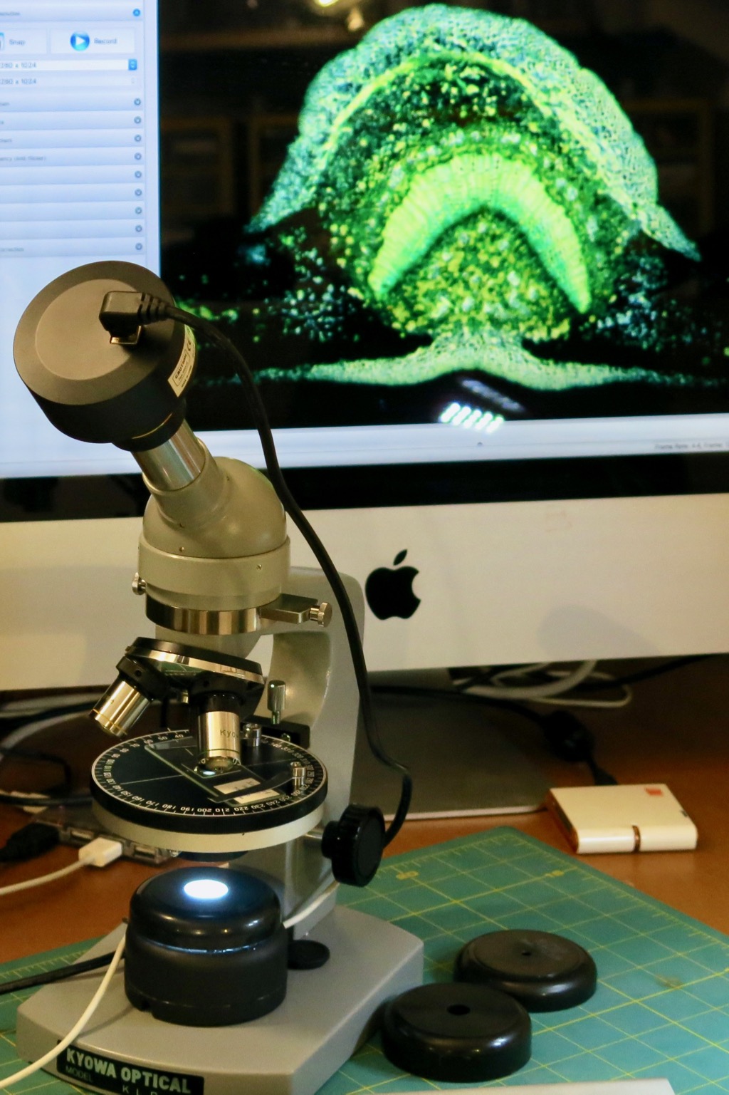
My 42 year old Kyowa polarizing microscope, shown at left, now has a home-made lighting system which runs off any USB port. A diffuser made from a plastic container was added. Three plastic aperture-caps, made from old paint test-pots, were drilled with different central hole sizes of 5, 10 and 18 mm. This controlled the extent of the illumination. The contrast and resolution was improved. The images were nearly as good as those from a research-quality microscope.
The inexpensive Omax 1.3 megapixel digital camera is sufficient for most purposes, as discussed below. This camera would also work well with the basic AmScope and Swift monocular microscopes discussed above.
Useful References
Getting the Best Out of a Basic Microscope is about lighting techniques to obtain high quality results, using simple paper light-diffusers to improve resolution and contrast. Professional results can be obtained with just a little preparation.
What Price Optics shows there are only minor differences in the quality of the observed image when viewing a marine Cocceneis diatom, using a range of 100X objectives. The objectives have an age range from recent to more than 100 years old and a 100 to 1 price range.
Microscopy of Nature shows the beauty of nature and confirms that good results can be obtained with almost any microscope. Rolf Vossen is also the author of the previous two links.
Teaching Microscopy to Young Children is worth looking at. This is essentially a very good microscopy lesson-plan for young children. Microscopes similar to the links above are recommended and their application is much wider than just biology.
Pippa's Progress shows amateur science with a microscope for young people with videos, information sheets and a very nice book.
MicrobeHunter has videos, podcasts, a forum and much more about microscopy.
Microscopy-UK is a good reference site about microscopy with many contributed articles.
Eyepieces and Objectives
A replacement AmScope 6 objective set and a modern AmScope wide-field 10X-18 mm eyepiece can revive an old and well-used microscope. 10X is the eyepiece magnification. 18mm is the eyepiece field of view, or diameter, of the intermediate image located 10 mm below the top of the eyepiece-tube for a DIN standard microscope. The observed field of view, using a 10X objective, is 18/10 = 1.8 mm. This can be tested by observing a perspex ruler.
It is not uncommon for old microscopes to have scratched or delaminated lenses, so new low-cost objectives and eyepieces can be a major improvement.
For many Leitz microscopes the intermediate image is 18 mm below the top of the eyepiece-tube, with Leitz standard optics fitted. For many other brands this value is 10 mm. This distance is a design property of the eyepiece. If you place a virtual image at this point it will be in focus, when viewed. This virtual image is usually inside the eyepiece and the top lens is used to observe it.
Field of view (mm) for a 10X-18 mm eyepiece with 4X to 100X objectives and a 160 mm tube length
- 4.50 mm, 4X
- 1.80 mm, 10X
- 0.90 mm, 20X
- 0.45 mm, 40x
- 0.30 mm, 60X
- 0.18 mm, 100X
Note that a 25x eyepiece sold with some microscopes, to achieve the marketing gimmick of 1000x to 2500X, is not going to reveal any more detail. It will be hard to use, particularly with glasses, because the eye needs to be very close to see the full field of view. The correct way to achieve extremely high magnification is with a 60X objective or a 100X oil-immersion objective. An eyepiece magnification range from 5X to 16X is more comfortable to use. 10X is a good choice.
If glasses are worn, an eyepiece with a high eye-point may be needed. This is the distance from the eye to the eyepiece where the full field of view is seen. If the eye is too far from or too close to the eyepiece this will not be the case. Lower magnification eyepieces often have higher eye-points.
One of the best eyepieces I have used is the Leitz Periplan 10X or 12.5X. They are not too expensive second-hand. With a 3.5X Leitz achromatic objective there is a little chromatic aberration at the image edge, although the field stop shows none. There is also a Leitz Periplan 8X eyepiece which has a higher eye-point and a 26 mm field of view. With a 4X objective the observed field of view is 26/4 = 6.5 mm. A second-hand Olympus WF10X eyepiece is also very good. With a 4X achromatic objective it shows a slightly flatter field of view with a little chromatic aberration at the edges.
On my Kyowa polarizing microscope, with a 160 mm tube length, the AmScope objectives worked well. The stage micrometer was sharp almost to the edges using either an Olympus WF10X eyepiece or a AmScope wide-field 10X-18 mm eyepiece.
If the original polarizing microscope objectives are in good condition, it is best to retain them as they are strain free. Uncorrected low-cost objectives may add some extra retardation similar to that seen with compensating plates. With crossed polars the background may not be completely black. With compensators the colours may be shifted. For routine bright-field microscopy they work fine.
My Leitz Dialux polarizing microscope has a 170 mm tube length. Leica states that 10 mm tube length differences will only matter for objective magnifications lower than 16X. However the AmScope 4X and 10X objectives do perform well for camera and eyepiece viewing, perhaps a little better than my Kyowa microscope. The built-in compensation of the Leitz Periplan eyepieces and the effect of 10 mm extra tube length have combined to produce a good result with the AmScope objectives.
The viewing is even better when a pair of AmScope wide-field 10X-18 mm eyepieces are used. Some my other objective and eyepiece combinations do perform terribly, with strong chromatic aberration and curvature of field. All combinations of objectives and eyepieces are worth testing. I have been fortunate with the lenses I am now using.
The image below was taken on my old Kyowa polarizing microscope using 4X Plan, 20X, and 60X achromatic AmScope objectives and an Omax 1.3 MP camera. The cropped field width shown is about 45% when compared with the table above. A USB LED light source was used and is shown in the lighting section below. The slide also looks very good using, either the AmScope WF10X-18 mm eyepiece, or the Olympus WF10X eyepiece.

The AmScope wide-field 10X-18 mm eyepieces are surprisingly good. The viewing is very sharp with nice contrast. Unlike the Olympus WF10X eyepiece, there is no chromatic aberration at the edge using either a Leitz 3.5X achromatic objective or an AmScope 4X achromatic objective. There is a low curvature of field and good sharpness near the edges with all the AmScope DIN achromatic objectives. This matching eyepiece and objective combination works very well with the 160 and 170 mm tube-length polarizing microscopes I have here.
Vertically cropped images of a 2 mm long Leitz stage-micrometer with bar intervals of 0.01 mm are shown below. These images were taken with a 3.1 MP Omax camera on my Leitz Dialux polarizing microscope. The eyepiece views were slightly sharper.

Suggested Additional Objectives
A good compromise is to fit a 60X objective in place of the 40X or 100X objective. Oil is not needed. For some applications, such as observing pond life, replacing the 10X objective with a 20X objective allows more detail to be seen, while still allowing the tracking of subjects.
Note that the generic AmScope objectives and eyepieces are the same as on many other brands of microscope. I would fit 20X, and 60X, objectives rather than the supplied 40X and 100X objectives. The 20X and 60X objectives, as noted above, are not an expensive addition. I also have an AmScope 4X Plan Achromatic Objective, which is perfect for photography. This objective is parfocal with the AmScope DIN achromatic objectives.
Lighting
I have converted all my microscopes to LED illumination. With LED illumination excess brightness can be a problem. LEDs are not lasers, but they can be very bright. LEDs have a major advantage over tungsten-filament white light sources, with no colour change when they are dimmed.
Initially I used a 3.3 volt, 20 mA, white LED. Using a 12 volt power supply a 435 ohm resistor [(12-3.3)/.02 = 435] was needed in series to keep the current to less than 20 mA. A "preferred value" 470 ohm resistor was therefore used. I found that for general use this provided more than sufficient light for bright-field work. For dark-field and polarized light work more brightness was needed. The measured LED voltage increases with current. At the maximum rated current a white LED forward voltage can range from about 3 to 3.6 volts.
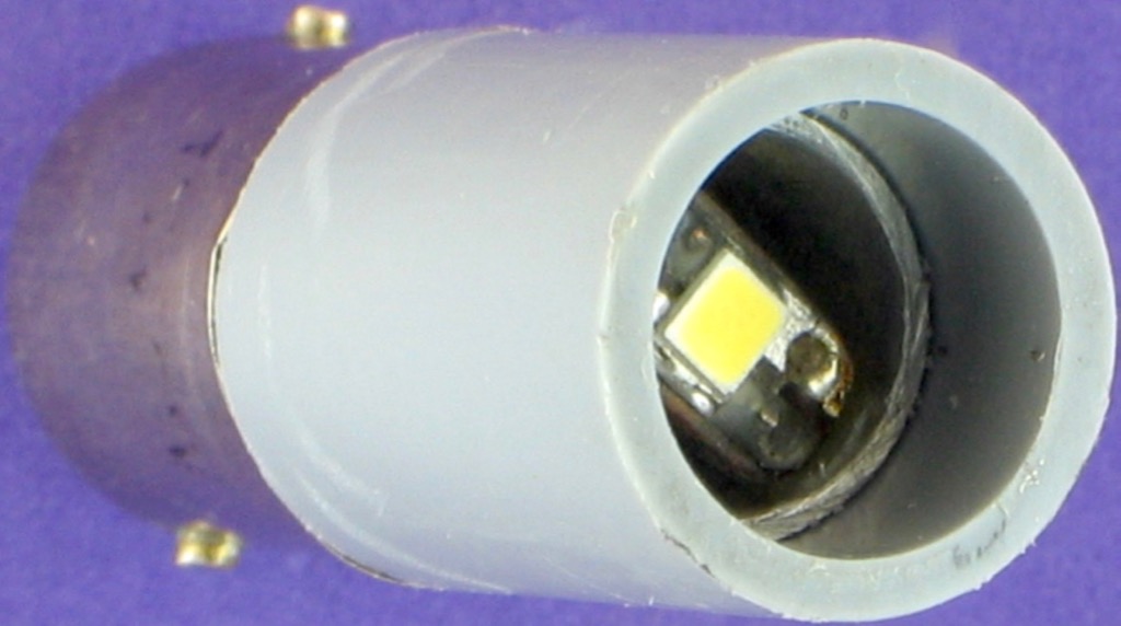
Then I used a bare white LED chip recycled from an old light bulb. Light bulbs package 3 or 4 blue LEDs per chip. The blue LEDs are covered with a yellow fluorescent layer to make a very even white light source. The illuminated surface area of 6 mm2 is much larger than a typical packaged white LED. I mounted the LED in the same position as the filament would be in the unusual and expensive Leitz tungsten lamp.
A recycled cool-white 3 LED chip from an old light bulb had a measured forward voltage of 8.45 volts when run at 50 mA. I put two 33 ohm resistors in series for a good light output at up to 12 volts.
USB light Sources
I have recently prepared some microscope lights powered by a USB hub or a USB power-bank. Many second-hand microscopes have mirrors or illumination based on obsolete lightbulbs and heavy power supplies. Converting to LED illumination removes a source of heat and often improves the viewing experience. USB illuminated microscopes are self-contained, portable and useful tools. Everything fits inside the microscope case. It is also greener, since older microscopes can now have an extended working life.
The USB 2.0 specified power output is about 2.5 watts, or five volts at 500 mA. For my Kyowa polarizing microscope I converted a $5 camp-light which originally ran directly off 3 AAA cells at 4.5 volts. The flat 16 mm diameter LED, mounted on an aluminium heat-sink, was ideal for this purpose. A switch wired in series with a 10 ohm resistor and a 200 ohm wire-wound potentiometer produced LED currents from 12 to 168 mA using a 5.1 volt USB power-bank. I have now updated to the Mosfet circuit, below-left, to control this LED source. The 22 ohm series resistance can be as low as 3.3 ohms, depending on the LED specifications.
I used white translucent plastic as a light diffuser. Above this I added the bottom half of an old condenser comprising a diaphragm and a field lens. The illumination was very bright and even. I added this light in place of the original microscope mirror. The inside of this simple light is shown at right.

An earlier and even simpler USB light is described in the Beginner's section above. This light is now used to provide transmitted illumination for an old Cook, Troughton and Simms M6100 Greenough stereoscopic microscope. This microscope is shown at right, along with a view of the sub-stage lighting. For incident lighting there are two LED lights costing $7 each, so the total cost of lighting is under $20. A steel plate, added to the mirror cradle, engages with the magnetic base of the lamp to hold it steady.

For my Leitz Dialux polarizing microscope I am now testing the 16 mm diameter camp light LED, described above, because the white balance is better and it is very easy to align. So far it is working well and it is probably the best light source I have tested at a very reasonable price. The white LED consists of a 16 mm diameter light-yellow phosphor disc dotted with 16 small blue LEDs mounted on an aluminium heat-sink.
The light source position and the condenser height needs to be adjusted so these two sources are properly mixed to produce white light. This is no different from defocussing a filament image. Alternatively, only one layer of Scotch Magic Tape located 10 mm above the light source is sufficient to produce uniform white light. The best filter I have used came from a mildly translucent plastic bag used to package cereal.
Because the light source is 16 mm in diameter a longer focal length field lens can be used in front of the light source. I used a plano-convex lens with a focal length of about 40 mm. The convex side faced the light source. The lens, or the LED, was positioned until the the base of the field-diaphragm was slightly more than fully illuminated. The LED position and centering is no longer a critical adjustment, so it could simply be fixed in place on a bracket.
A simple 2N7000 N-Channel Mosfet circuit, shown above at left, uses a 100 kohm potentiometer to control the LED brightness when connected to a 5 volt USB power supply. The LED current can be varied from 0 to 100 mA. In the camp light the dropping resistor is 1.8 ohms so this light source can operate at over 700 mA or approximately 2 watts, with good heat sinking. The value of the 150 kohm resistor can be lowered to 100 kohm if the LED intensity is still changing when the potentiometer reaches full scale.
The LED runs fine with an extra 3.3 ohm dropping resistor at 200mA. For higher currents a different Mosfet would be required. The Mosfet dissipates about 240 mW at this current and it only gets mildly warm. In this application a small metal heat-sink is glued to the Mosfet. For my purposes the light level produced is sufficient with some margin for improvement.
Choosing a Microscope Camera
The simplest way to take photos through a microscope is to use a smartphone and a good quality microscope adapter. The Gosky Universal Smartphone Adapter Mount looks to be thoughtfully designed. The smartphone can be rigidly held at the right distance from the eyepiece and aligned with the optical axis. The Swift Universal Smartphone Adapter SPA-E28 should also work well. The smartphone is easier to remove without disturbing the setup.
The photo below is a hand-held photo taken while holding my iPhone 6 cell-phone over the eyepiece of my old Olympus POS polarizing microscope. The field-diameter is 1.8 mm. A 16 mm diameter white LED was used for illumination and some thin white plastic as a light diffuser. A simple mosfet dimmer was used, as described above.

Microscope Resolution
Optimum microscope resolution assumes:
- The sample is prepared perfectly.
- The cover slip is perfect and uniform at 0.17 mm thick.
- The slides are optically perfect at a constant 1 mm thick.
- The sample medium has a suitable refractive index.
- The lighting is optimum, but there is a trade-off between resolution and good contrast.
- The glass in the microscope optics is clean, properly positioned and optically correct.
- The objective turret is accurately made and the objectives are centered.
- The microscope and camera is free from vibrations while the picture is taken.
- The sample is exactly focussed, which is impossible with samples with a finite thickness - stacking can help.
- The stage is not slowly moving out of focus.
- The objects on the slide are almost stationary during the exposure.
- The slide is perpendicular to the optical axis of the microscope.
- The camera relay optics are matched to the objectives.
In reality few of these statements are entirely true.
The 4X and 10X objectives have the best and similar resolutions. Using Abbe's formula the microscope resolution can be calculated:
d = 550/2NA where 550 is the wavelength in nm of yellow light and NA is the numerical aperture of the objective.
For a 10X achromatic objective with 0.25 NA the resolution d = 275/NA = 1100 nm or twice the wavelength of the light. This calculation applies to any class of objective and any medium such as oil used for mounting and viewing. NA is printed on the objective. Divide that number into 275 and you get the resolution in nm.
For the usual range of microscope objectives the observed resolution, across a diameter and expressed as pixels, ranges from about 1800 pixels at 4x to 1100 pixels at 40X. At 60X the resolution reduces to about 930 pixels.
Cameras would typically sample about 67% of these horizontal resolution values, expressed as pixels. So camera requirements for routine microscopy can be rather modest - typically in the 1 to 5 MP range. See Numerical aperture and resolution and the camera notes below.
Camera Resolution
A digital camera is useful as a recording device, but it almost never displays the additional detail seen by the eye. The eye can, to a degree, focus through the image to reveal more layers of detail at the same time.
My ideal camera would have medium resolution and do real-time stacking of images so the display is in focus everywhere. Astronomers are making good progress with this technique and there are a few microscopy papers such as Rapid-Image-Acquisition-Method-For-Focus-Stacking-In-Microscopy by Douglas Clark and Brian brown.
The sample width seen with my 3.2MP camera, using a 10X achromatic objective, is 1.25 mm or 1250000 nm and the required horizontal camera resolution is therefore 1250000/1100 or 1136 pixels. The sample height seen with the 3.2MP camera is 0.94 mm or 940000 nm and the required vertical camera resolution is therefore 854 pixels. So a practical camera resolution is about 1MP. Bayer sampling of colour will increase the actual camera resolution requirements making the 2MP and 3.2MP cameras slightly better choices. In contrast, the properties of an affordable viewing screen may reduce the need for extra megapixels. A 5MP camera would meet all needs but the frame-rate may be too low and the noise greater.
Matching Camera to Microscope Resolution is a useful tutorial which assumes perfect optics. A 3 MP camera would be about optimum using this guide. Required camera resolution for photography through the microscope can be simply demonstrated by taking an image at two resolutions, namely 3 MP and 12 MP. Anything above 3 MP shows only minimal improvements in detail with most microscopes. This argument only applies to microscopes, not telescopes.
If camera resolution is an issue, try using a stronger objective.
If the microscope is used to produce large fine-art prints then the the requirements for the microscope optics and the camera will become much more expensive. There will be some improvements in resolution, field flatness and colour accuracy with the best optics.
Field Curvature and Resolution
Although the image is sharp to the eye, there is almost always field curvature. There is a region towards the edge of the image circle which is not so sharp. This effectively reduces resolution when the objective image is projected onto the flat sensor surface.
The eyes can adjust focus a bit, when using the eyepieces. Fortunately only the sharper middle-part of the objective image is sampled by the camera. Expensive plan objectives do produce nearly flat fields, so more camera resolution might be justified, particularly at low magnifications.
Resolution and LCD screens
A 21 inch computer monitor is typically 2.1 MP and not all of that 1920x1080 pixel area would be used in practice. Using my recent prescription reading glasses I can just resolve the dots on this screen at a viewing distance of 300 mm. At my normal viewing distance I don't see them. So my personal resolution requirements seem to be in the 2 MP range for a full-screen image.
A 1.3 MP camera has 1280 pixels horizontally and 1024 pixels vertically. If just the vertical resolution of a typical LCD display, at 1080 pixels, is considered then a 1.3 MP camera should be satisfactory. In general, the lower resolution cameras are less noisy and can cope with a wider range of illumination levels. Omax offers 0.75x, 0.5x and 0.37x C-mount reduction lenses which can be chosen to optimise the camera viewing area.
Not all the computer LCD screen area is used. The Touplite imaging program has a display window of 1500x900 pixels, which is smaller than the usable area on a 21.5 inch 1920x1080 pixel LCD display. This expands to 1500x942 pixels if the Mac toolbar is not displayed. So the maximum number of pixels that can be displayed using Touplite is 1.4 MP.
Resolution and Publishing
For some users, publishing requirements may dictate the required camera resolution. An image printed at 300 dots per inch on half an A4 sized page, with generous margins, would need to have a resolution of about 2 MP. But typically many papers have montages of much smaller images. Each small image focuses on a particular detail. So again, 1.3 MP may do. Note that many scanning electron microscopes produce images with similar pixel numbers.
Cameras and Trinocular Adaptors
Some microscopes have inconvenient trinocular adaptors which do not fit standard eyepieces. This makes many microscope cameras difficult to fit. There are a few options:
- Use one of the two inserts supplied with many cameras, if the trinocular tube is too large.
- Get a 0.5x C-mount adaptor from the microscope maker, or from a supplier like
AmScope or
Omax.
- Modify the microscope fitting by replacing the existing tube with a 23.2 mm ID tube.
The simplest way is to cut the existing tube near the base.
Two stepped metal collars are machined, one to take a 23.2 mm ID tube, and the other to take the smaller diameter original tube.
- Make a replacement fitting using a lathe or CNC machine.
- Machine the exterior of the relay lens housing to suit.
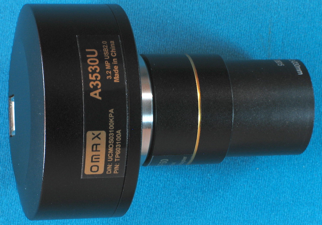
Four Omax Microscope Cameras
For my purposes there were four Omax cameras of interest.
- 1.3 MP with 1280x1024 pixels at 15 frames per second, 640x512 pixels at 26 fps and 320x256 pixels at 50 fps.
Signal to noise ratio is 44 dB and the dynamic range is 71 dB.
The pixel size is 3.6 x 3.6 microns.
The supplied reducing lens has a magnification of 0.37X.
- 2.0 MP with 1600x1200 pixels at 16 frames per second and 800x600 pixels at 50 fps.
Signal to noise ratio is 43 dB and the dynamic range is 61 dB.
The pixel size is 3.2 x 3.2 microns.
The supplied reducing lens has a magnification of 0.5X.
- 3.2 MP with 2048x1536 pixels at 8 frames per second, 1024x768 pixels at 22 fps and 680x510 pixels at 43 fps.
Signal to noise ratio is 43 dB and the dynamic range is 61 dB.
The pixel size is 3.2 x 3.2 microns.
The supplied reducing lens has a magnification of 0.5X.
- 5 MP with 2592x1944 pixels at 5 frames per second, 1280x960 pixels at 18 fps and 640x480 pixels at 60 fps.
Signal to noise ratio is 40.5 dB and the dynamic range is 66.5 dB.
The pixel size is 2.2 x 2.2 microns.
The supplied reducing lens has a magnification of 0.5X.
The Touplite application has fixed magnifications of 10%, 20%, 25%, 33%, 50%, 67%, 75%, 100%, 150%, 200%, 300% and 400%. These magnifications can combine with the camera pixel settings to vertically fill the software viewing window at 1500x900 pixels on a 1920x1080 screen. The 1.3 MP camera matches reasonably well at 100% magnification with 1280x1024 pixels in the recorded image. The 2.0 MP camera matches almost exactly at 75% magnification to give a 1200x900 pixel on-screen picture and 1600x1200 pixels in the recorded image.
The aspect ratio of the 1.3 MP camera is 4 by 5. The other cameras all have a 3 by 4 aspect ratio.
The other cameras could use medium resolution for viewing and high resolution for photography. Touplite has this option. At medium resolution the 5 MP camera is a good match for the software viewing area with a reasonable frame rate. An Apple 21.5 inch Retina screen shows 2304 vertical pixels so the Touplite viewing height is about 1912 pixels. This matches the 5 MP camera at full resolution but the low 5 fps frame rate may be annoying. The optics of a high quality microscope actually provides a somewhat lower resolution, particularly in air, for the reasons described above. Note that the higher resolution cameras have a lower dynamic range, they have lower frame rates and they are noisier. As computers evolve, a USB-3.0 or USB-C camera might be a better option in the future. In my case cost was an issue.
With dim illumination the exposure time may increase to 350 ms to compensate. If there are moving subjects the resulting mages may be blurred. If the lighting is sufficiently bright the camera specifications should be met. High resolution cameras tend to have low frame rates with longer exposure times. This is because the pixel size is smaller and therefore less sensitive.
The USB-2.0 interface limits the data rate. A small object moving within a stationary field of view would probably be rendered better than in a complex field of other moving objects. A coloured image at 1200x1024 pixels has 3x256 colour levels making for a total data size of 943,718,300 M bits or 118 Megabytes of 8 bit information. Compression and buffering reduces this. The typical 30 MB/s data rate of a good USB-2.0 connection is stressed if too much image content is changing at the same time. The frame rates are higher if auto-exposure is disabled in Touplite. USB-3.0 is better for good video but it is more expensive.
Omax 1.3 MP Microscope Camera
I ended up purchasing an Omax 1.3 MP camera SKU:A3513U at US$117.99 plus shipping. The camera performs well and delivers very nice images, some of which are shown below and at right. In retrospect, the 2 MP camera may be a good choice as it can better fill the software viewing window, using the fixed Touplite magnification selections. The image is 7% wider, the frame rate is faster and the dynamic range is slightly less than the 1.3 MP camera. The higher frame rate is probably not fully realised with USB-2.0.
I also purchased a 0.37x reducing lens for my original 2 MP JEPCAM which was made from an adapted web camera. Some images from this camera are shown at right. Modern microscope cameras are sufficiently inexpensive, and of such high quality, that it is no longer worthwhile modifying web cameras to suit.
I use the supplied Touplite software on my iMac and ImageJ for cropping and adding scale-bars. The Windows version of the supplied software is ToupView. It is more comprehensive and has more editing features, including scale bars. Touplite on the iMac is fine for my purposes. The latest 2025 Mac version of Touplite now has most of the useful features of ToupView for Windows. I can now do image stacking for an improved depth of field and image stitching for a larger field of view.
1.3 MP Camera Field Width, Camera Field Height, WF-10X Eyepiece Field Diameter, Objective Magnification. Microscope with 160 mm tube length.
- 3.00 mm, 2.40 mm, 4.50 mm, 4x
- 1.20 mm, 0.86 mm, 1.80 mm, 10X
- 0.60 mm, 0.48 mm, 0.90 mm, 20X
- 0.30 mm, 0.24 mm, 0.45 mm, 40X
- 0.19 mm, 0.16 mm, 0.30 mm, 60X
- 0.11 mm, 0.10 mm, 0.18 mm, 100X
This camera sees 67% of the viewing diameter seen through a WF10X eyepiece.
Omax 3.2 MP Microscope Camera
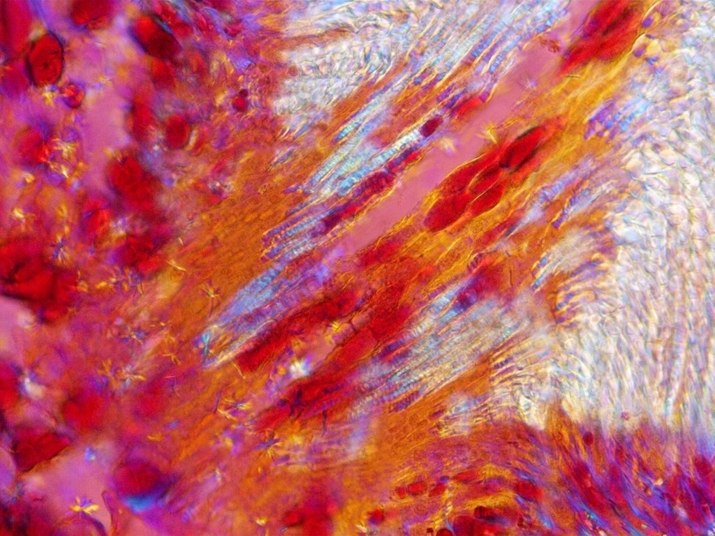
I now have an Omax 3.2 MP camera SKU.A3530U at US$166 plus shipping. The performance is very good and there is a marginal improvement in the image quality at some magnifications. For most purposes there is no difference, but I now have a camera to use with one of my other microscopes. I can use both cameras with one computer and I can easily switch between them in Touplite. As a first purchase this, or the 2MP camera SKU:A3520U at U$139.99, would definitely be my camera choices.
3.2 MP Camera Field Width, Camera Field Height, WF-10X Eyepiece Field Diameter, Objective Magnification. Microscope with 160 mm tube length.
- 3.10 mm, 2.30 mm, 4.50 mm, 4X
- 1.25 mm, 0.94 mm, 1.80 mm, 10X
- 0.62 mm, 0.47 mm, 0.90 mm, 20X
- 0.31 mm, 0.23 mm, 0.45 mm, 40X
- 0.21 mm, 0.16 mm, 0.30 mm, 60X
- 0.12 mm, 0.10 mm, 0.18 mm, 100X
This camera sees 69% of the viewing diameter seen through a WF10X eyepiece.
Polarized Light Microscopy
Polarized light microscopy can produce some spectacular coloured images from ordinary subjects, such as fibres, sand, dust or even sugar crystals. With low cost microscopes some Polaroid can be added to one port in the stage aperture disk and a Polaroid cap added to the top of the eyepiece, as mentioned in the lesson-plan above. Alternatively two caps could be made, one for the eyepiece and another set below the slide. If there are prisms or mirrors in the light path, rotate the top Polaroid for the maximum light transmission using non-polarised light. Insert the lower Polaroid below the sample slide and rotate until most of the background light is extinguished.
Polaroid can be recycled from old LCD screens or old sunglasses. Clear thin plastic sheeting can also be added under the upper Polaroid cap or on top of the lower Polaroid to replicate sensitive-tint viewing. A clearer image will be obtained if the plastic sheets are in the lower position. Choose enough sheets to produce a magenta colour when inserted and rotated between crossed Polaroids. This allows some of the functions of a Leitz polarizing microscope to be duplicated.

Circular polarized filters for digital cameras can also be used. They are plain polarizers combined with a 1/4 wave plate. The effect is similar to adding plastic sheets between the polarizers. Use circular polarizers, one above and one below the sample with the threaded sides towards the sample. They won't need to be rotated for good viewing. There is only a slight change in the background when rotated, which is due to the 1/4 wave plate being fully effective at only one wavelength. The sample colours will be rich and often appearing less sensitive to slide orientation if two orders of the same colour are seen.
Polarized Light
Polarized light is used in geology to help to identify minerals in thin section. It is also used widely for the identification of particles and fibres. A sample may exhibit birefringence between crossed polars. There is an additional rotation in polarization direction which allows the crystal to become visible. If the refractive index of the crystal varies with direction then two polarized light streams are emitted with different strengths and retardations. This will produce colours because there is destructive interference of the two streams of polarized white light at particular wavelengths Some colours are removed from the white light spectrum. The colours are repeated, but become muted, as the retardation increases. The colours observed are summarised on a Michel Levy Interference Chart.
The McCrone Research Institute is an Illinois not-for-profit educational and scientific research organisation located in Chicago. Polarized light microscopy is used extensively by this organisation. It offers courses in microscopy and does research in support of its educational activities. Many of the links at right also provide more information about polarized light microscopy.
Compensating Plates and Imaging
One of the useful things that compensators do is to shift the colours in samples into a range suitable for viewing or photography. Also there are references at right which describe the measurements that can be made, using compensators, to identify sample phases. The main properties of these devices are described here.
-
A full-wave compensating plate, set at 45 degrees to one polarizer, rotates polarized light by 360 degrees.
The retardation is now at a maximum of about 550 nm.
The compensator then shifts the interference colour wavelengths, from samples, by about 550 nm.
This wavelength of 550 nm is called the retardation.
This means that low birefringent samples with almost monochrome interference colours are now brightly coloured.
Yellow and blue are often seen, but many colours can be produced.
The colours seen with samples can be found from the
Michel Levy Interference Chart.
The colours and extinction angles can be used to identify some samples or to determine the optical sign.
-
A 1/2 wave compensating plate, set at 45 degrees to one polarizer, rotates polarized light by 180 degrees.
The retardation is now at a maximum of about 275 nm.
The effect of this retardation is that when a second polarizer is added the light is always in near extinction when this polarizer is rotated.
Light, without any sample present, is always blocked.
These plates are not common, but for photographic work they are quite helpful.
-
A 1/4 wave compensating plate, set at 45 degrees to one polarizer rotates polarized light by 90 degrees.
The retardation is now at a maximum of about 137 nm.
This generates circular polarized light.
Two polarizers with a single 1/4 wave plate between will always transmit light when the second polarizer is rotated.
-
Two circular polarizers, with their built-in 1/4 wave plates facing each other, behave like the 1/2 wave case above.
The polarizers are always in extinction, blocking any light, only if one is left-handed and the other right handed.
There will be a slight variation in colour as one circular polarizer is turned.
A single circular polarizer viewed in a mirror, to make an opposite-handed pair, will also appear dark at all orientations.
The mirror can be used as part of a lighting system if opposite-handed circular polarizers are not available.
-
Lastly, two polarizers, without any retardation, will block light twice per revolution when one polarizer is rotated.
A sample set between the polarizers will show maximum retardation colours when the stage is rotated 45 degrees away from the 4 extinction positions.
-
Commercial full-wave plate retardations vary a bit, typically over a range of 530 to 560 nm.
1/4 wave plates vary over a smaller range.
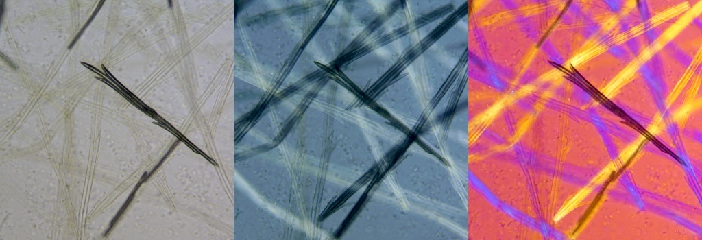
The image below shows some Dandelion seed-head fibres mounted in a medium of almost the same refractive index. The left-hand bright-field image is not very clear, with some loss of detail. The middle image, viewed in polarized light with a 1/4 wave compensating plate inserted, shows more detail. The right-hand image is viewed with in polarized light with a full-wave compensating plate inserted. The shading and colours depend on the fibre orientation. One nearly vertical fibre almost matches the background. Rotating the stage shows all fibres in a good light, in sequence. Each image field-width is 0.45 mm.
Everyday items, with no colours, may become brightly coloured in full-wave compensated polarized-light. Non crystalline transparent materials, like glass, are not coloured unless they are stressed.
My disposable face-mask has 3 layers. The outer layers are randomly arranged 0.015mm diameter spun-bond polypropylene fibres with a pattern of melt-dots holding everything together. Part of a melt-dot can be seen in the left-hand photo below. The inner layer comprises 0.005mm diameter felted fibres, with no melt-dots and is supported by the much stronger outer layers. Each layer is about 0.2mm thick. All layers melt at around 150°C when heated.
The mask is permeable and may provide only partial protection from objects the size of tiny viruses. Fortunately, expelled corona viruses are usually associated with droplets and particles, which are easier to trap because they are much larger. Somewhere along the tortuous path through the mask a droplet or particle will stick to a fibre. A mask is better than no mask, but social-distancing is also required.
The images below show the outer and middle mask layers in polarized light with full wave compensation. I used a Leitz 16X objective and the image width is 0.56 mm. For the inner layer I used my stereo microscope and two circular polarizers. I used a 3X objective and the image width is 3 mm. With the half-wave compensation the fibre colours do not change with orientation.

Sensitive Tint Imaging Improvements
I have experimented occasionally with polarized light microscopy since 1974 when I worked in the DSIR. I found that modern plastic materials can behave like compensators. Some plastics used for packaging are typically biaxial and can offer retardations greater than 100 nm, depending on the thickness and the method of manufacture. Thinner plastics can be used for trimming the colours from a standard 530 nm full wave compensating plate, to improve contrast.
Nicely coloured images for transparent samples, with low contrast and low birefringence, can be obtained by supplementing the effect of a gypsum full-wave "sensitive tint" plate . This is equivalent to trimming the thickness of the full-wave plate, producing the best possible contrast. Alternatively with an additional 1/4 wave compensator plate placed in the condenser, above the polarizer. It can be simply rotated until the colours are suitable.
If a Berek or Quartz-Wedge compensator is inserted, a fairly sharp boundary is seen between first order yellow and second order blue. This is a narrow region showing good contrast and detail. The compensated lighting is trimmed to match this boundary. Some low birefringent samples are now seen as distinctive combinations of yellow and blue. The whole field of view now has a nice magenta background colour.
This is mainly an aid for photography. For quantitative work just use the gypsum "sensitive tint" full-wave plate.
The following image shows first-order yellow bordering second-order blue, using a Berek compensator which tilts a gypsum or magnesium fluoride plate. This creates a range of thicknesses equivalent to several orders of retardation. The corresponding interference colours are produced when the Berek compensator is inserted between crossed polars. Sample details are seen more clearly at the magenta border between first-order yellow and second-order blue. The image is a little unsharp because the tilted Berek compensator plate is located just above the objective holder.
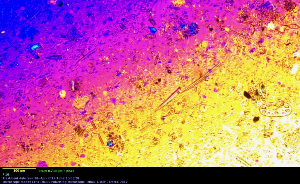
For future use I calibrated the Berek Compensator using sets of up to 3 stacked 147.3 nm or 530 nm compensating plates. With a compensating plate, oriented at 45 degrees from extinction on the stage, there were two tilt readings where the field of view went dark in cross polarized light.
Let R1 = reading 1 and R2 = reading 2. The tilt angle is X = (R1 - R2)/2. Tilt angles were plotted against the total plate retardation, as the plates were stacked on the stage and set at 45 degrees. The retardation Y was a good fit to a simple power curve Y = 2.64 * X1.9853 where X = tilt angle (degrees) and Y = retardation wavelength (nm). Angles (X) below 10 degrees produced a retardation (Y) error of about 2%, otherwise about 1%. I can now measure retardations from near zero to about 1600 nm.
For the photo below of the Diatom - Nitzschia circumsuta BW-113, prepared by Stuart Stidolph in 1982, I inserted a strain-free perspex plate, covered with a clear 0.006 mm thick mylar plastic film, above the condenser polarizer. The mylar film was originally used in XRF sample preparation. It sticks to Perspex electrostatically. It has a maximum retardation of about 200 nm which is high, given the thickness. This is possibly due to the thin mylar being more severely extruded than packaging plastics. Here the mylar is oriented to produce a much smaller retardation. My Perspex sheet came from Bunnings and I was pleased to see no sign of birefringence between crossed polars. As far as I can tell it plays no role in the improved image properties observed. I inserted a full wave gypsum "sensitive tint" compensator into the standard slot above the objective.
The mylar film was oriented on the perspex until the background colour bordered between first-order yellow and second-order blue. The background colour is set a bit more towards yellow than a normal full wave plate. In the past, I have also used mylar film layers from an oven bag, as a near full-wave compensator. Any slightly birefringent sample either shifts the observed colour towards blue or yellow, depending on the sample structure, and on the orientation.
For microscopes without a filter holder above the condenser polarizer, some mylar films can simply be adhered to the bottom of the slide. With the gypsum compensator inserted, the stage is rotated until a suitably coloured image is obtained. The camera is then rotated to restore the desired image orientation on the screen.

Sensitive Tint the Low Cost Way
Many microscopists do not have access to a polarizing microscope but they do have some Polaroid filters. The polarizing caps for the eyepiece and light source, mentioned above, are easy to add. Turn one filter until the background view is dark.
One layer of Clear Scotch Packaging Tape, adhered to a slide and set at 45 degrees is a good nearly first-order compensator. Rotate until a nice blue background is produced in polarized light. The camera can also be rotated to restore the slide image to the desired orientation. Removing the adhesive with kerosene allows the Scotch Tape to be just slipped under the slide. Other sources of plastic compensators are clear packaging, CD boxes, some report covers and oven bags.
Circular Polarizers
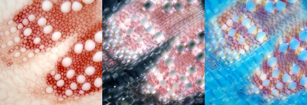
For whole-slide macro photography I took many photos for students using circular polarizers above and below the sample. The intention was to produce a coloured general view of the slide. The circular polarizer provided a polarizer and a 1/4 wave retarding plate in one component. The camera lens side of each polarizer, containing the quarter wave plate, faced the sample slide. The 1/2 wave length total retardation produces a dark background at nearly all polarizer orientations and strong sample colours.
Circular polarizers come in left and right handed versions. One of each is needed. You need to test pairs for complete extinction as one polarizer is rotated. For some pairs just plain polarized light remains and there is little extinction of light. Check for 360 degree extinction when the camera sides of the filters face each other. Some polarizers may not be exactly quarter wave or the alignment of the 1/4 wave filter to the polarizing filter may not be exact. I have only two circular polarizers out of five where everything works well.
3d Glasses as Circular Polarizers
Rather than buying an extra, expensive circular polarizer, the lenses from some old 3d glasses could be used. Only one lens will work with a photographic circular polarizer, producing near extinction at all orientations. Set the 3d glasses lens on the illumination side of the sample and the optically good photographic circular polarizer for viewing or imaging. The eye side of the lens from the 3d glasses should face away from the illumination and towards the sample. The glass in the photographic circular polarizer may need to be flipped if the polarizer is screwed into a mounting.
Alternatively both 3d lenses could be used with no other circular polarizers required. For best results the lenses should be arranged at 90 degrees to each other.
Samples in Circular Polarized Light
I had some polypropylene hairnets for use at some commercial sites where some basic hygiene was required. There are surprising delights when simple everyday objects are examined in this light. The colours of the melt spots will vary with thickness settings during manufacture. I like the repeatable results I can get with essentially no critical microscope adjustments. I used a Kyowa stereo microscope for all the circular polarized images below.

This image field width is 4 mm. The hairnet is advertised as "non-woven, 100 % spun-bond polypropylene". The fibres are about 13 microns (0.013 mm) in diameter. There is a pattern of small melt dots holding everything together. In transmitted, polarized, 1/2 wave retarded light, clear polypropylene fibres with the same composition and diameter all show the similar yellow colours according to my colour meter. Where they cross, the colours tend towards a brown-yellow with less red and a little blue present. There is little change in colours with orientation. The larger and clear melt spots are coloured various shades of blue and cyan in this lighting.
I use these hairnets as dust covers for my old microscopes and other equipment. Note that disposable non-woven face masks and some other PPE use similar materials and construction methods.
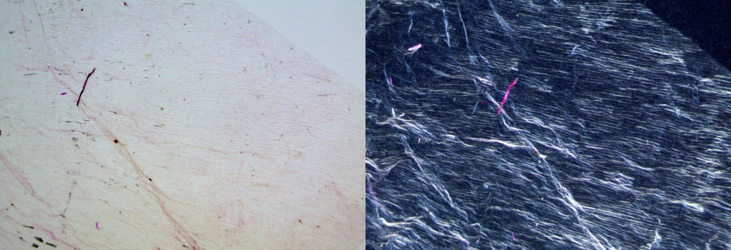
The Dandelion fibre image below has low birefringent colours which don't depend much on fibre orientation. There are slight colour changes when the stage is rotated. Some fibres are dark-pigmented so I rotated the polarizer away from complete extinction for better viewing. Much less detail is seen using normal bright-field illumination, as shown above. The image field width is about 1.2 mm.
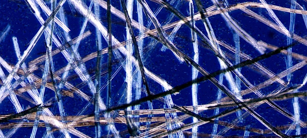
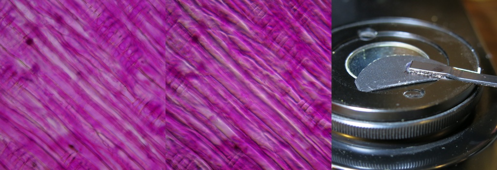
At its best an image with circular polarizers looks a lot like a dark-field image with stable added colours, if there is sufficient birefringence. With careful alignment there is almost no colour change as the sample is rotated. This occurs when the background is the darkest. It varies, when rotated, from black to a very dark blue with the best polarizers. The brightfield onion skin image below, at left, shows little detail. There is much more detail with two circular polarizers at right. All orientations of the sample look almost the same, unlike when viewing with cross polarized light. The images each have field-widths of 3 mm.
A LED backlight with a white diffuser provided illumination, with the circular polarizers set in place above and below the sample
Circular Polarizers on my Leitz Dialux Polarizing Microscope
The standard condenser which came with many Leitz polarizing microscopes has a swing-out polarizer. I added a circular polarizer above the light exit in the microscope base. The camera side of this polarizer faces the condenser above. If a 3d circular polarizing lens is used, the concave eye-side of this lens faces the light source below. Only one lens, with the correct handedness, will work.
A polarizing microscope usually allows a 1/4 wave compensator to be inserted into the slot above the objective. The top polarizer is moved into place. With the the correct handed circular polarizers in place below, the field should become dark. Rotate the lower polarizer until the background is black. The microscope is now ready and the view will be similar to that obtained with my kyowa stereo microscope.
The following image shows some citric acid crystals at 16X and 3.5X The image widths are 0.78 mm and 3.5 mm respectively. For the right hand image I rotated the bottom polarizer to change the background from black to dark blue.

With a simple and low cost microscope using the 3d circular polarizing lenses should be sufficient. One lens can be cut to fit just above whatever condensing lens is present. The other lens could be cut to about the size of a cover slip and sit directly above the slide. This arrangement is a good option since the microscope optics are unlikely to be strain-free. The 40X objective also probably can't be used because it may focus too close. My Kyowa stereo microscope was easy to set up with standard photographic circular polarizers and a simple backlight.
To make a microscope slide of citric acid crystals I spread out a few drops of a nearly saturated solution in water. I added some more citric acid crystals at one corner until they stopped dissolving. Crystals grew over the next few days exhibiting many interesting forms.
Dark-Field, Rheinberg and Circular-Oblique Illumination
Dark-Field Stops
To create some dark-field stops I cut out some plastic disks from a black plastic binder cover, using some hole punches. For the larger disks I cut around a coin or a washer of the right size. I used Blu-Tac to hold the coin steady while cutting with scissors. The disks range in size from 5 mm to 16 mm. I made some perspex supports, shown below, to allow the disks to be inserted in the condenser filter slot above the polarizer.
The diaphragm is used to control the illuminated annulus width. The annulus of light comes to a point focus at the sample. With the right sized disk a second annulus of light is formed just outside the objective lens field of view. Only scattered light from the sample enters the objective lens. The sample is usually bright, sometimes with diffraction colours, while the background is dark.
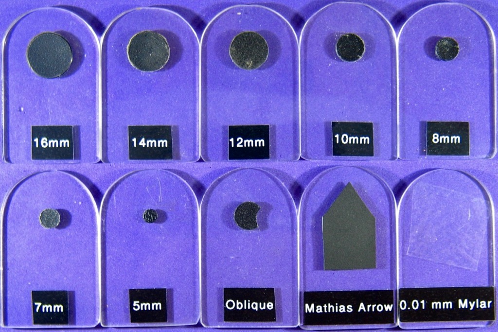
The larger disks suit the more powerful objectives, although they are quite critical to align for good dark-field work. A 10X to 20X objective is a good choice for initial work. The disks are placed on the Perspex support and secured with a spot of Blu-Tac. The Perspex support is inserted into the filter slot of the microscope condenser. The Blu-Tac allows the disk to be moved and centred. Some lateral movement of the Perspex support is possible. Careful condenser focusing and centering is usually needed.
If no dark-field illumination is seen, open the condenser diaphragm and raise or lower the condenser. Removing the eyepiece and looking down the tube will help with centering the disk and choosing the right size. The usual bright illumination seen at the rear lens of the objective should only just be obscured. A Bertrand lens can be used to see an enlarged view.
Dark-Field Setup
A Leitz microscope dark-field kit has stops 6, 11, 16 and 19 mm in diameter for the 4X, 10X, 20X and 40X objectives. There is no need to be too exact and the data here is a guide only. A modern Olympus microscope uses dark-field stops averaging 11, 17, 20, 23 and 25 mm in diameter for 4X, 10X, 20X 40X and 60X objectives.
My very old Olympus POS polarizing microscope has dark-field stops of about 13 mm for the 4X and the 10X objectives. A 20 mm diameter stop is suitable for a 40X objective, about 3 mm less than calculated for a modern Olympus condenser. Better results are obtained with the condenser set close to the sample slide.
Dark-Field Condenser
An item of interest to me is a commercial dark-field condenser which has easy to use centering adjustments. Some use reflecting optics to produce a ring of light which converges on the sample. Others use a disk, as already described. A typical NA range from 0.7 to 0.9 suits higher powered objectives.
Rheinberg illumination
Using a blue disk and a yellow backing produces Rheinberg illumination. Scattered light becomes yellow and the unscattered background becomes blue. Other colours can be used. Use darker colours such as blue or red for the disk and yellow, green or clear for the backing, as these colours will appear as highlights. The photos below were taken on my Kyowa polarizing microscope using a 10X objective and an Omax 1.3 MP camera. The image widths are approximately 1 mm. The pine-needle slide is old and the Canada Balsam is starting to crystallise. The epidermis ruptured during microtoming and some cell contents smeared to the left. Some of these details were not obvious with normal lighting.


Old red/blue stereo glasses are a good source of filter material. Coloured Cellophane is another. Cellophane may need to be stacked to increase colour density. Marker pens can also be used. For the stop you can use the hole in a suitable washer as a guide. Alternatively, drill a hole in a suitable template. Personally, I often use a simple clear filter with a dark-blue stop in the centre. The sample highlight colours are not altered.
Circular-Oblique Illumination
Circular-oblique illumination is less critical. An annular ring of light illuminates the sample but offsetting the disk means that the image has shading and relief, like in a good portrait. One disk has a semicircular cutout at the edge to provide two levels of oblique lighting and some shading for contrast. The setup is not dissimilar to the lighting setups used for portraiture and movies. More than one light source (the ring and the cutout) and some delicate shading (slightly off centre) can produce a nice image.
With the condenser top-lens near to the slide the illumination is usually dark-field. With the condenser higher still the illumination becomes circular-oblique as some annular light now enters the objective. This lighting works best with the stronger objectives. An improvement in resolution is usually observed with this illumination. Some of the references at right describe both techniques. Microscopy-UK has many articles of interest.


Diatom Preparation
One of the many methods for diatom preparation uses hydrogen peroxide, potassium dichromate, potassium permanganate, hydrochloric acid, sulfuric acid and nitric acid. In the late 1970s I replaced a similar process with my Plasma Asher for the inorganic analysis of blood samples. It was very effective for many toxicology samples and a number of laboratories around the world used similar schemes. This 2010 reference outlines the use of Plasma Ashing to directly process diatom samples on a microscope cover slip.
In 2009 we used Plasma Ashing to prepare a diatom sample directly on an electron microscope stub. The stub was set downstream from the RF plasma so no heating occurred. I have since modified the Plasma Asher so that the only reagent is oxygen generated from a small fuel cell. Air can also be used. The plasma slowly converts all organic material to carbon dioxide, without any heating. Both diatom references, below, used Plasma Ashing for sample preparation.
The Plasma Ashing can be monitored with a photo-diode. At the end of ashing a glow-discharge extends down the full length of the sample tube.
Berek Condenser
I am currently using a Berek polarizing condenser on my Leitz Dialux Polarizing microscope. This is a self-contained device with two diaphragms. The bottom diaphragm controls the light beam diameter while the top part behaves like a normal condenser, but with almost no chromatic aberration. The field diaphragm in the base of the microscope is normally left wide open.
The Berek condenser has no filter slot. The field aperture on the base of the microscope can be partially covered to provide either dark-field or oblique illumination. For the oblique image, below, I used a black semi-circular stop to make a crescent shaped opening. This opening obliquely illuminated the base of the condenser and is shown below, at right. The stop had 3 points of contact, one with the middle circular ridge and two with the inner edges of the the handle slot. The kinematic stop positioning is exactly the same each time it is used, meaning images taken at different times can be compared. The bright-field and oblique image field-widths are each 0.45 mm.
Stereo Microscopes
My Stereo Microscopes
I have two old stereo microscopes. One is a Kyowa stereo microscope with 10 and 30 times magnification. I added a bike LED front light shown at right for strong incident illumination. I also have a Cooke stereo microscope which is capable of both incident and transmitted light viewing. The magnifications are 15.6, 44 and 125 times.
Stereo Microscope Photography
The 1.3 MP Omax camera comes with an adapter, so it can fit an eyepiece tube of my Kyowa stereo microscope. In this setting the camera takes better photos than my 2 MP JEPCAM web camera. It can handle a wide range of light levels easily, as the hp35 calculator display photo below shows.
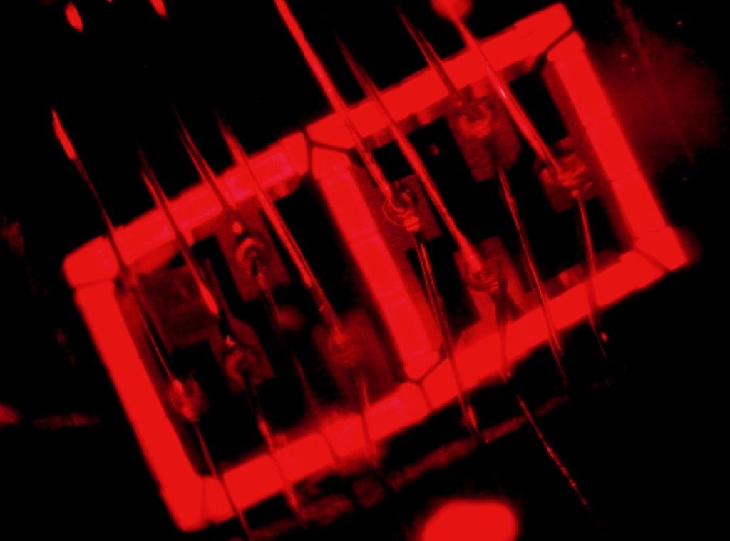
This microscope is occasionally fitted with two circular polarizers set up so the total retardation is about 275 nm, or 137.5 nm per polarizer. The photo below shows a mixture of cotton fibres, synthetic fibres and hair using this lighting.

Flat samples should be tilted upwards at the right by 7.5 degrees, if the camera replaces the left eyepiece. The sample will now be in focus from edge to edge. I made a tilting sub-stage from an old computer access cover. I also made a diffuse sub-stage light from a small $2.75 LED key-ring light and some white perspex. This runs off any USB port.
At 10X the horizontal field of view is 12 mm and at 30X it is 4 mm. For a good summary of stereo microscope photography Micro Tech Lab concisely covers the main issues.
Note that a normal compound microscope, using its lowest power objective, is a very nice incident-light microscope.
All that is needed is to arrange some lighting.
Digitech 5 MP USB Microscope
USB Microscope Upgrade
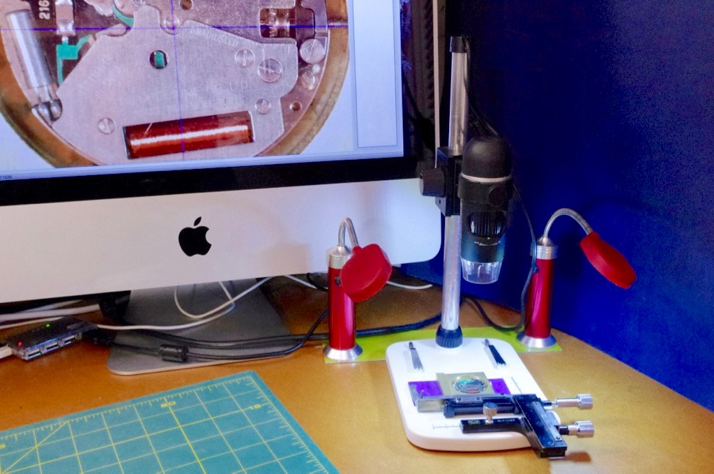
I purchased this microscope, shown at right, from Jaycar and modified it. The microscope is similar to the Celestron Handheld Digital Microscope Pro.
The focussing mechanism was a bit loose so I disassembled it and inserted shims to tighten it up. I placed the shims between the supporting screws and the body of the focussing mechanism. I extended the stand to a height of 280 mm using some 16 mm diameter polished aluminium tubing. This allowed the full camera focus range to be used. It is quite a good long working distance microscope.
I added an old x-y stage to help with sample positioning. I drilled a mounting hole into the microscope base tapped at 40 TPI to take the 1/8 inch Whitworth bolt. I also drilled two 1 mm diameter positioning holes.
To make the stand more rigid I removed the bottom of the plastic base and applied Araldite to the edges. I also applied some Araldite below the tubing holder so a further connection was made at the plastic base. After reassembly the stand was now remarkably stable at all magnifications.
At low magnifications the built-in lighting produced reflections on some objects. I added two $7 flexible LED lights to improve the lighting. They have magnetic bases and a rectangular metal plate holds them in place.
ImageJ and Scale-Bars
This microscope is now a reasonably professional instrument. I can use ImageJ instead of the supplied software. I use the ImageJ scale bar tool along with two white marks added to the camera focusing wheel. The left hand mark is placed on the right edge of the focussing wheel when it is turned fully to the right. The right hand mark is placed on the left edge of the focussing wheel when it is turned fully to the left. The field width is 1600 Pixels. For various settings of the focus the field width in mm is:
- 42 mm. RH mark at left. Working distance to shield - 175 mm.
- 25 mm. RH mark near left. Working distance to shield - 80 mm.
- 16 mm. RH mark mid left. Working distance to shield - 40 mm.
- 8 mm. RH mark centred. Working distance to shield - 7.5 mm.
- 6 mm. RH mark visible at right, light shield touching. Working distance to shield - 0 mm.
- 2 mm. LH mark centred, light shield touching. Working distance to shield - 0 mm.
- 1.7 mm. LH mark at right. Working distance to shield - 4 mm. This is the highest magnification.
The scale-bar shown below uses the highest magnification setting in transmitted light. The interval between bars is 0.01 mm. The field of view is only slightly smaller than seen using a compound microscope with a 10X WF18 eyepiece and a 10X objective.

Pentax Macro Camera
Lenses
My Pentax macro setup is shown above at right. The bellows lens extension on the Pentax digital camera uses a reversed 28 mm lens as the objective. Turning the lens around means the optical paths through the lens are similar to those in normal photography. The lens functions as the designer intended and image quality is high. Longer focal length lenses can be used for lower object magnifications. Normal microscope objectives can also be used. I use a special microscope objective which has a built-in diaphragm for depth of field control.
Canon Macro Cameras
Macro Adaptors
Shown above at right, a LED illuminated magnifying loupe is attached to a Canon A590 camera. An LA-DC52G Conversion Lens Adapter, or similar, is needed as a stable attachment device. This setup is small, portable and is suitable for field use.
A Canon G5 camera is mounted on my old Leica enlarger stand for close-up photography. This combination is also a very good document copy camera. A close-up lens can be fitted with a LA-DC58B Conversion Lens Adapter, or similar.
In the photo below a bubble level ensures all of the image is in focus if the sample table is also level. Placing a flat mirror on the sample table should result in a reflected and centered image of the camera lens. The camera is now parallel to the sample table.
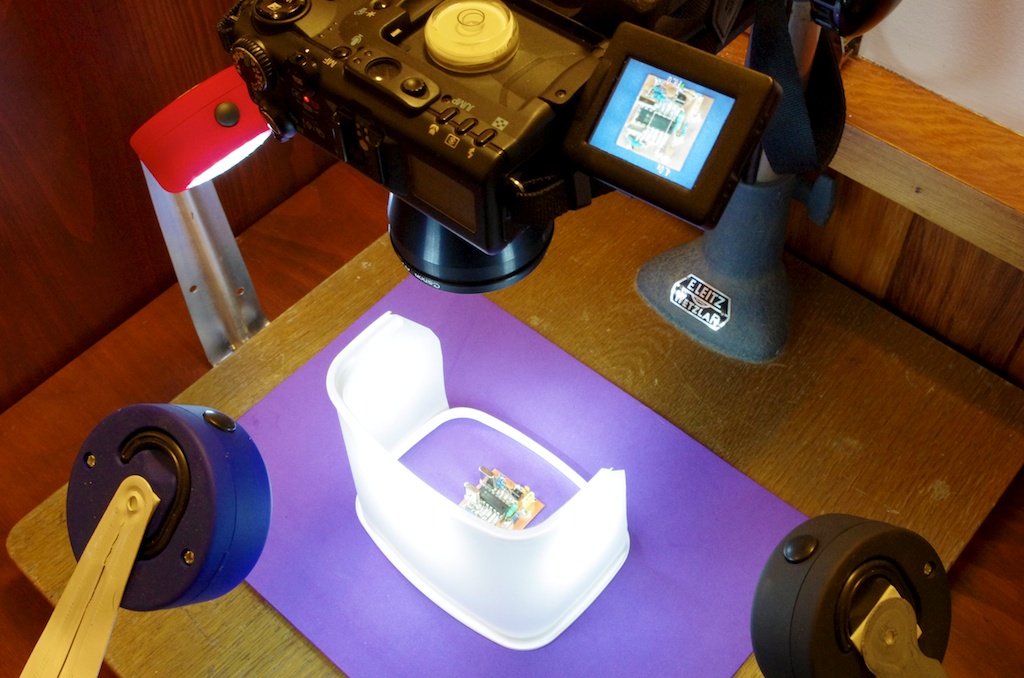
For photographing items, such as prints or books. I use a range of small USB powered LED lights and diffusers to provide illumination. The diffusers are recycled from old LED lightbulbs. A heavy perspex window helps to flatten pages. To save the binding a book only needs to be partly opened, as shown below. A black card obscures any items above the window, except the dark camera lens. This eliminates most reflections and improves contrast.

Publications
Two unusual Diatoms from New Zealand: Tabularia Variostriata a new species and Eunophora Berggrenii. Margaret A. Harper*, David G. Mann and John E. Patterson, Diatom Research (2009), Volume 24 (2), 291-306.
New diatom taxa from the world’s first Marine Bioblitz held in New Zealand: Skeletomastus a new genus, Skeletomastus coelatus nov. comb. and Pleurosigma inscriptura a new species. Margaret A. Harper*, John E. Patterson, John F. Harper, Acta Botanica Croatica 68 (2) 2009.
Oxygen Plasma Asher. J E Patterson. Analytical Chemistry, 51, 1978, 1087-1089
Microscopes
AmScopeEuromex Microscopes Holland
Leica Microsystems
Meiji Techno
Motic Europe
Nikon
Olympus
Omax
Swift
Zeiss
Education
Historical MicroscopesLeica Microscopy Knowledge Portal
Mathematical Microscope
MicrobeHunter
Micrographia
Microscopist.Net
Microscopy of Nature
Microscopy-UK
Microscope World
Modern Microscopy Journal
Molecular Expressions
MyScope
Nikon MicroscopyU
Olympus Microscopy Resource Centre
Pippa's Progress
Practical Microscopy
Project MICRO
WWW Virtual Library of Microscopy
Virtual Microscope
Zeiss Campus
Groups
Biomedical Imaging Research UnitMicroscopy-UK
McCrone Research Institute
Microscopy Society of America
Microscopy New Zealand
The Quekett Microscopical Club
Royal Microscopical Society
Imaging
ADIAC Diatom Image DatabaseFiji - ImageJ together with Java, Java 3D and a lot of plugins
ImageJ - Image processing and analysis in Java - PC, Mac or Linux
Microscopy and Mineral Images
1/4 wave plates and imaging
Inexpensive Macro Photography
Insect Macro Photography
Mounting Digicams With Zoom Lenses Over The Microscope
Cameras
AmScope Microscope CamerasMicroscope Cameras from Microscope.com
Numerical aperture and resolution
Omax Camera Software
Omax Microscope Cameras
Proscitech - Search for Cameras
ProScope 5 MP Microscope Camera
ToupView Quick Help
Click the photos below to enlarge. Use the browser "back control" to return.
 Inside a USB Microscope Light
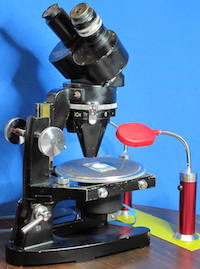 Cook, Troughton and Simms M6100 Greenough stereoscopic microscope
 LED sub-stage lighting
 LED bike lamp illuminator
 JEPCAM with DSE 2 MP webcam inside
 JEPCAM showing 10 micron spaced bars. 100X objective
 JEPCAM - Oamaru diatom, 20X objective
 JEPCAM - Sponge gourd stem, 40X objective
 JEPCAM - Wheat grain, 40X objective with added scale bar in ImageJ
 Plastic bag seal cross section
 Diatom - Pleurosigma angulatum, dark-field image, 40X objective, 2 MP JEPCAM
 Diatom - Pleurosigma angulatum, oblique illumination, 63x objective, 2 MP JEPCAM
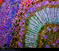 Leaf stem - Nerium Oleander, polarized illumination with dual compensators, 10X objective, Omax 1.3 MP camera
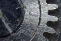 Pentax macro camera - old watch movement
 Canon Powershot G5 macro camera - tooth section
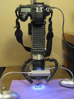 Pentax macro camera
 Digitech 5 MP USB camera
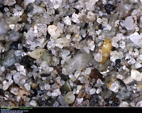 Digitech 5 MP USB camera, Barrytown sand sample
 Canon A590 Macro camera
