Mocon Profiler repair
Updated 9 November 2023
Introduction
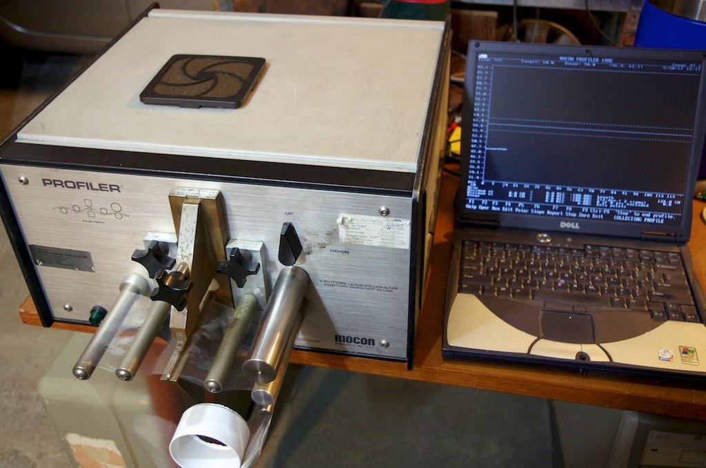
The Mocon 140e Profiler is an instrument designed to measure the thickness of blown multilayer plastic films offline. Sample loops are cut and measured for thickness around the whole loop. Manufacturing standards are set for uniformity and absolute thickness. The Mocon 140e profiler is used in a laboratory situation to help meet these standards. A client company engaged me to look at the possible repair of two faulty instruments.
Unfortunately the two instruments that the client owned had both stopped measuring thickness. Instead a noisy random plot was observed. An oscillator failure was the most likely cause. Available options were repair or the purchase of a replacement instrument. Replacement oscillators were not available and in the past were very expensive. The Mocon 140e Profiler is no longer made. It has been replaced by a profiler from Solvtech. In this case the need for a solution was urgent as a production trial was about to be started.
Operating Principle.
The Mocon 140e is essentially a capacitance-based thickness gauge. Measures have been taken to improve instrument stability by using a temperature-controlled oscillator unit.
At the sample a 9.95Mhz RF signal is applied to a strip electrode assembly. The sample is driven over the electrode by a motorised roller. At a nearby variable reference capacitor another 9.95Mhz signal is seen.
The two RF signals are applied to a diode mixer where sum and difference signals are created. The sum signal is just below 20 Mhz and is filtered out by a RF choke and a low pass filter. The difference signal is set by the variable capacitor to a frequency of 420Hz in the absence of any sample. This audio signal passes through a band pass filter and is sent to the digital logic board. Here the period is accurately determined by counting pulses from a 20 MHz reference oscillator. The period of the oscillation varies directly with the capacitance and therefore the film thickness.
It should be noted that no technical information on the oscillators was available so I had to work everything out from the circuit boards. An oscilloscope and a frequency meter were a great help.
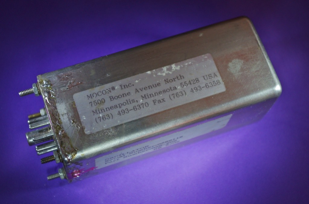
The 9.95 MHZ RF signals are derived from twin crystal oscillators which are held in a temperature-controlled oven at about 60°C. This prevents temperature drift. The crystals are connected either to the electrode assembly or the reference capacitor. These capacitors can pull the crystal frequency by an amount dependent on their value. The capacitance of the electrode assembly depends on the film thickness. The design is not significantly different from the common Theremin musical instrument.
First Oscillator Repair
In order to repair the oscillators I had to gain access. They were inside metal cans which were soldered shut. For the first repair I held the inverted can in a large vice which acted as a heat sink. I used a 100 watt soldering iron and some desoldering braid to remove most of the solder. I then used a flat bladed knife to split the seal. The can could then be opened by easing the base out. This oscillator showed clear signs of overheating due to a temperature control failure. There was also evidence of previous repairs.
The most obvious fault observed was the complete detachment of a toroidal RF choke which had just been glued to the audio filter circuit board. No mechanical support was provided so failure was essentially guaranteed. The shell of the choke was extremely brittle and the leads had also detached. Because of this I was unable to determine a value. I replaced it with a 470μH RF choke. There were a few other faulty components and soldering faults. In particular the two potentiometers on the oscillator board were noisy due to oxidation. They were replaced. Once all the repairs were completed I had two oscillators running and Audio from the mixer. A few other circuit trace repairs were made. Bad soldering on the oven temperature control circuit had caused it to overheat. The can was closed with the support of two self tapping screws. The oscillator tested out fine when installed in the Mocon 140e.
Second Oscillator Repair.
The second oscillator showed similar symptoms to the first except it did not overheat. On opening the can the problem was obvious. The RF choke had again fallen off the circuit board. The shell was extremely brittle and the leads had again broken. Replacement with a 470μH RF choke restored normal operation.
Result
In conclusion, both oscillators were guaranteed to fail by poor RF choke design and unsuitable mounting. Vibration or thermal shock would certainly cause failure. The standard of construction of the first oscillator was extremely poor. The second oscillator was a major improvement, except for the RF choke. I saw nothing in the design which was exotic or novel. Basically there were two crystal oscillators, a mixer, a RF filter and an audio band pass filter set at 420Hz. Many radio receivers have similar circuitry.
Oscillator Design
I was asked if I could design a spare oscillator. My immediate thought was to use digital logic rather than conventional analog RF circuitry. Since no modulation was imposed on the RF signals considerable simplification could be achieved. Options included using CMOS oscillators running into an up/down counter. The output would be an audio signal. I eventually settled on a design using an exclusive OR gate as a mixer. My initial design used three ICs. The final design used just one IC.
I used a 74HC86 exclusive OR gate with a 5 volt regulated power supply. The IC has 4 dual input gates. From the truth table I saw that two gates could be used as inverters if one input was tied to +5 volts. Two 10MHz crystal oscillators were designed around these gates. A third gate was wired as a mixer. The two inputs were connected to the outputs of the two 10MHz oscillators. The fourth gate, wired as an inverter, was connected to the mixer output. A 100k ohm resistor was used, along with the stray gate capacitance, to filter out the 20MHz mixer signal, leaving only an audio frequency square wave at the output. An additional RF filter and a low pass filter allowed a clean audio signal to be presented to the logic circuit of the Mocon 140e Profiler. I assembled the prototype on a small piece of Veroboard. Care was taken with RF bypassing and tracks were kept short. Components with known low temperature drifts were used.
Initially I did not use any temperature control. I selected numbered crystal pairs for low drift by choosing from a selection of 10 crystals. Pairs were plugged into a circuit which was tested at 20°C and 30°C for audio frequency stability. A few crystal pairs produced extremely low drift. In a controlled temperature environment drift would be minimal. I also insulated the aluminium box internally.
On testing, this oscillator produced a similar performance to the original oscillator. It was likely that any remaining drift would be the result of normal expansion and contraction of the electrode assembly with temperature. Installation simply involves plugging the unit in and setting the output frequency to 420Hz with the trimmer capacitor. There will be two positions where 420Hz is seen. Adjust to 0Hz and then wind the trimmer anticlockwise until 420Hz is observed. Many digital multimeters can measure frequency. The best sampling point is at J9 on the logic board.
RF circuit construction is like building a guitar. Some designs sound better than others. The final oscillator design used a standard Manhattan RF construction technique. This produced a signal with improved stability when viewed on a high speed oscilloscope. This was primarily due to the copper ground plane and the very short wiring path lengths.
Temperature Controlled Oscillator
By mounting the crystals on the other side of the board there is room to add a full temperature control circuit using a thermistor and an operational amplifier. Considerable work has been done to achieve a stable result. The circuit is deceptively simple. The additional circuitry is shown at right and a temperature plot is shown below.

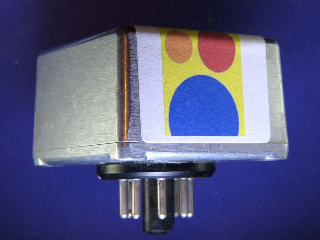
The revised circuit performs as well as the original Mocon design. It is much more compact and it requires only the +15 volt power supply. It is a drop-in replacement for the original. Four pads of Blu-Tac adhesive are placed under the case to prevent any vibration or movement. A temperature controlled oscillator can be built and tested for NZ$3000.

JEPSPECTRO - Home Page
Email: replace at with @
jepattersonatactrix.co.nz
Mocon
Solvtech
Click the photos below to enlarge. Use the browser "back control" to return.
 Mocon 140e profiler. Oscillator with insulation.
 Missing RF choke. This brittle glue residue was used to support it.
 Damaged RF choke with a missing lead.
 Mocon 140e profiler with the new oscillator installed.
 Oscillator signal at the logic board input.
 Circuit 11/06/2012.
 Components under 74HC86 IC - revised design 04/03/2014
 Oscillator layout - revised design 04/03/2014
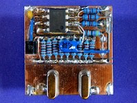 Temperature controller with heating resistors and thermistor - revised design 04/03/2014
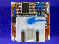 Thick aluminium heat-sink added to the temperature control circuit - revised design 04/03/2014
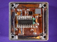 Circuit in insulated box before wiring to plug on base - revised design 04/03/2014